8 . CONTROLLER
![]() In order to prevent an electric shock and shortcircuit, be sure to turn power off before performing work by touchingthe interior parts of the product.
In order to prevent an electric shock and shortcircuit, be sure to turn power off before performing work by touchingthe interior parts of the product.
Be careful so as not to damage wirings. Damaged wiring cancause an electric shock or short circuit accident.
This work should be performed by the Location's Serviceman.Performing work by non-technical personnel can cause shock hazard.
Don not touch places other than those specified. Touchingplaces not specified can cause an electric shock accident.
In case the Controller's value movements are irregular in theTEST mode, adjust or replace the Volume in the following procedure.
8 - 1 ADJUSTMENT AND REPLACEMENT OF SWING VOLUME

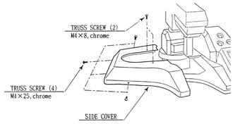
(1.) By taking off a total of 6 screws, remove the Side Cover(L,R).
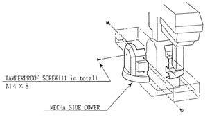
(2.) By taking off a total of 11 screws, remove Mecha SideCover (L,R).

(3.) Take off the 2 screws to remove the Hide Plate.
8 - 2 V.R. ADJUSTMENT
(1.) Loosen the 2 screws which secure the V.R> Bracket tomove the V.R. Bracket.
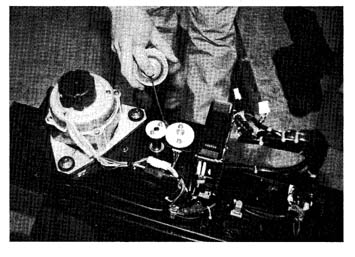
(2.) Move the V.R. Bracket to disengage ADJUST GEAR mesh andmove the V.R. shaft in the manner so that the V.R. shaft cut portionfaces the oppisite side of ADJUST GEAR as shown.
(3.) Have the gears meshed and tighten the 2 screws.
(4.) Slowly swing the Controller up/down, and left/right tocheck if the value exceeded the moveable range of the V.R.
(5.) After finishing adjustments, be sure to set sighting onthe AIM SET screen in the TEST MODE.
8 - 3 V.R. REPLACEMENT
![]() In order to prevent electric shock and short circuit,be sure to turn off power before performing work by touching theinterior parts of the product.
In order to prevent electric shock and short circuit,be sure to turn off power before performing work by touching theinterior parts of the product.
(1.) By Removing the Cord Clamp, first remove V.R. yellow 3Pfor up/down and V.R. white 3P for left/right. Take off the 2 screwswhich secure the V.R. Bracket to remove the V.R.
(2.) Remove the Volume Gear from the V.R. to replace V.R.
(3.) After replacing the V.R., perform work by following theprocedure as per V.R. ADJUSTMENT ABOVE.

8 - 3 REPLACEMENT OF TRIGGER SW
![]()
In order to prevent an electric shock and short circuitaccident, be sure to turn power off before performing work bytouching the interior parts.
Be careful so as not to damage wirings. Damaged wiringscan cause an electric shock or short circuit accident. Do nottouch places other than those specified. Touching places not specifiedcan cause an electric shock or short circuit accident.
When the TRIGGER is pulled, if ON is not shown in the TRIGGERdisplay in the TEST menu "INPUT TEST" screen, the MICROSW may be malfunctioning. In that case, it is necessary to replacethe MICRO SW.
REMOVING THE GRIP
(1) Take off 7 TAMPERPROOF SCREW's A and remoe COVER RIGHT.
(2) Take off 5 TAMPERPROOF SCREW's A, take out COVER BRACKET, and remove COVER LEFT while paying attention to the wires.
(3) Disconnect the CONNECTOR which is connected to the GRIP.
(4) Take off the 6 U NUTS to remove the GRIP.