ASSEMBLY CHECK
In the test mode, ensure that assembly has been made correctly,and that the IC board is satisfactory. In the test mode, performthe following tests.
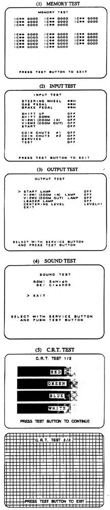
(1) Selecting the memory test from the test menu causes theon-board memory to be tested automatically. The game board issatisfactory if the display beside each IC shows GOOD.
(2) Selecting the input test causes the screen on which eachVR and switch are tested to appear. Press each switch. For thecoin inlet switch test, insert a coin from the inlet with thecoin chute door being open. If the display beside each switchindicates "ON'' the switch and wiring connections are satisfactory.Check the display of VR value for the steering wheel and acceleratorand brake. If the VR values are not satisfactory, refer to themechanical adjustments section.
(3) In the output test mode, carry out lamp test to ensurethat each lamp lights up satisfactorily.
(4) In the test mode, selecting sound test causes the screenin which sound related board and wiring connections are checkedto be displayed. Be sure to check that the sound is satisfactorilyemitted from each speaker and the sound volume is appropriate.
(5) In the test mode, selecting CRT test allows the monitoradjustment screens to be shown. Although monitor adjustments havebeen made at the time of shipping, make judgement if adjustmentsare needed by watching the test screens. If adjustments are needed,refer to the monitor adjustment section of this manual.
Perform all of the above mentioned inspections on a monthlybasis.