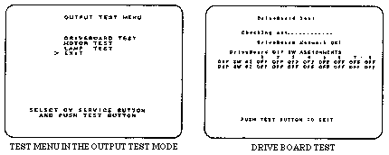
In the OUTPUT TEST, connections between IC Boards, the status
of each motor and lamp can be checked. In this mode. periodically
check these items.
In the menu mode. selecting OUTPUT TEST causes the menu (FIG.
8. 11 a) in the OUTPUT TEST mode to appear on the screen. Select
the desired test item in the OUTPUT TEST mode. Upon finishing
each test, first return the OUTPUT TEST menu to the screen, and
then choose EXIT to return to the menu screen and exit from the
test mode.

In the OUTPUT TEST menu mode, selecting DRIVE BOARD TEST allows
for checking connections between and functioning of the Drive
BD and Game BD as well as each V. R. and motors. After checking,
if "Drive Board Network; is OK!" is displayed. the testing
is satisfactory. For irregularity, ERROR display will be indicated.
Check connections between the Drive Board, the Game Board, each
V. R. and motor. Also check each V. R. and motor.
"Drive Board DIP SW ASSIGNMENTS" displays DIP SW setting
on the Drive Board at the time of Drive Board test. When DIP SW
setting is changed. be sure to turn the power off and then turn
it back on again to make the setting change effective.
For the operation of this machine. set all of the dip switches
to OFF. Make sure that all are set to OFF in this screen mode.
Press either TEST button or START button to return the OUTPUT
TEST menu mode to the screen.
STOP: IMPORTANT!
In this machine, DIP SW setting is for in-factory check ing. For
actual operation. set all the DIP SWes to OFF. Setting to ON may
not be appropriate for practical operation.