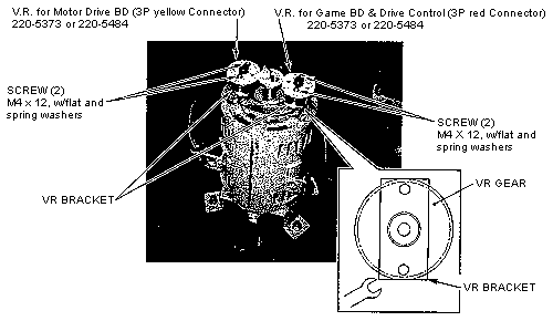
FIGURE 62: STEERING WHEEL ADJUSTMENT
POTENTIOMETER REPLACEMENT
The gear near the RED cable is connected to the Motor Drive
Board. The gear near the YELLOW cable is connected to the Game
and Drive Control Boards. Refer to Figure 62 for parts locations.
- Turn off and unplug the Indy 500 Twin game.
- Remove the Control Panel.
- Disconnect the three 3-pin wiring harnesses (WHITE: Power,
RED: Game Board and Drive Control Board, YELLOW: Motor Drive
Board).
- Loosen the two hex bolts under the appropriate outer gear,
and remove the bracket and gear.
- Replace the gear and bracket.
- Mesh the gears to secure the bracket. Be sure that the gear
is fully engaged and tighten the bracket screws.
- Connect the three 3-pin wiring harnesses (WHITE: Power, RED:
Game Board and Drive Control Board, YELLOW: Motor Drive Board).
- Reinstall the Control Panel.
- Set the Steering Wheel variable values in the Control Range
("Volume") menu.

