- CAUTION! Connecting the CRT and PCB
For combining the CRT and PCB, use the specified part No.
to maintain the status of adjustments made at the factory The
anode of the CRT itself will be accumulatively charged as time
elapses, generating high-tension voltage which is very dangerous.
The monitor should be used with the Chassis, CRT and PCB assembled.
When repair, etc., is required at the time of malfunctioning,
be sure to send it in an "as is assembled" condition.
If these are disassembled, what's charged to said high tension
voltage can be discharged, causing a very hazardous situation.
Therefore, under no circumstances should it be disassembled.
- Static Electricity
Touching the CRT surface sometimes causes you to slightly feel
electricity. This is because the CRT surfaces are subject to
static and will not adversely affect the human body.
- Installation and removal
Ensure that the Magnetizer Coil, FBT (Fly-Back Transformer),
Anode Lead and Focus Lead are not positioned close to the sheet
metal work's sharp edges, etc. and avoid damaging the insulated
portions so as not to cause electric shock and malfunctioning.
(For the name of parts, refer to the above figures).
MONITOR ADJUSTMENT
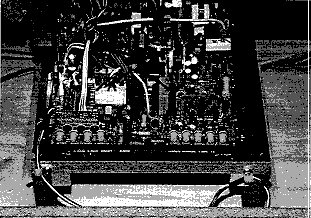
The monitor adjustment knobs are located inside the upper rear
access panel, as shown in Figure 50. Remove the upper rear service
panel to make adjustments to the monitor in conjunction with the
CRT Test Menu. The function of each control is shown in Figure
51.
CAUTION!
Do not operate adjustment knobs without a good reason.
Monitor operates on HIGH VOLTAGE - use caution when adjusting.
Use a plastic screwdriver when adjusting monitor.

FIGURE 50: MONITOR CONTROLS LOCATION

