[Previous page][Next page][Table of Contents]
7 - 2 TEST MODE
This mainly checks if the operation of the game BD is accurate, and allows for COIN
ASSIGNMENTS/GAME ASSIGNMENTS setting and Projector adjustments.
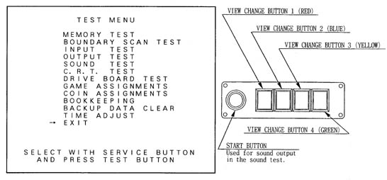
Push the TEST BUTTON to cause the following TEST MENU to appear:
By pushing the SERVICE BUTTON, bring the ">" mark to the desired item and press the TEST BUTTON. This will select the item to be tested.
After the test is complete, move the ">" mark to "EXIT" and press the TEST BUTTON to return to game mode.
7 - 3 MEMORY TEST
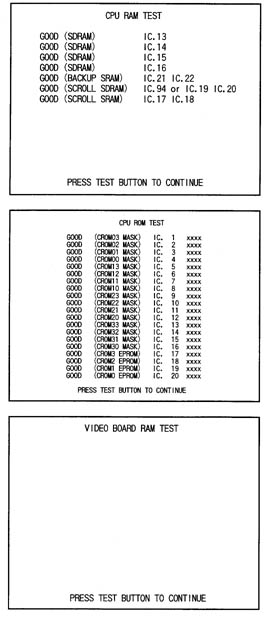
The MEMORY TEST mode is for checking the on-BD memory IC functioning.
"GOOD" is displayed for normal ICs and "BAD" is displayed for abnormal ICs.
When the test is completed, if the
display is as shown left, it is
satisfactory.
After finishing the test, pressing the TEST BUTTON allows the
MENU MODE to return on the screen.
IF THE TEST TIME FOR THE MEMORY TEST EXCEEDS 5 MINUTES THE IC BOARD MAY BE DEFECTIVE.
 7 - 5 INPUT TEST
Press the TEST BUTTON to have the menu mode return on the screen.
Using the Decision (SET) button instead of TEST BUTTON will not allow for exiting from the Input Test Mode. Press the SET BUTTON and SELECT BUTTON (UP).
By opening the Coin Chute Door, insert a coin from the Coin Inlet to check the Coin Chute Tower.
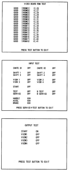
When INPUT TEST is selected, the MONITOR will show the following, allowing you to watch the status of each switch and the value of each V.R. of the cabinet to be viewed
On the screen, periodically check the status of each switch & V.R.
By pressing each switch, if the display on the right-hand side of the name of each switch changes to ON from OFF, the SW and the wiring connections are satisfactory.
PITCH refers to the Switch for the left/right Foot Pedal's UP/DOWN. Normally, this is ON and stepping on the Pedal's front side causes the Switch to become off.
7 - 6 OUTPUT TEST
Choose OUTPUT TEST to cause the following lower screen to appear. In this test,
check the status of each lamp.Pressing the TEST BUTTON causes "ON" to be displayed and the corresponding lamp lights up. Pressing the TEST BUTTON again causes "OFF" to be displayed and the lamp goes off. The Foot Controller is locked with the Slide Lock in the ON status, and Unlocked to become free with the Slide Lock in the OFF status.
Press the test Button to return to the MENU MODE.
7 - 7 SOUND TEST
This enables sound used in the game to be checked. Sound related memory and each speaker are checked.
Press the SERVICE BUTTON to bring the arrow to the desired sound item to be tested. SE refers to sound effects and BGM refers to background music.
Each time the SERVICE BUTTON is pressed, the numeral displayed on the screen counts up and sound is admitted.
Bring the ">" to EXIT and press the TEST BUTTON to return to the MENU MODE.
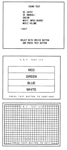
7 - 8 C.R.T. TEST
Select C.R.T. TEST to cause the MONITOR to display the screen shown left, allowing MONITOR adjustment status to be checked.
Periodically check the MONITOR adjustment status on this screen.
The screen (1/2) enables color adjustment check to be performed. The color bar of each of the 4 colors, i.e.,red, green, blue, and white, is the darkest at the extreme left and becomes brighter towards the extreme right.
Press the TEST BUTTON to shift to the next screen (2/2).
The screen (2/2) allows screen size and distortion to be tested.
Check if the CROSSHATCH FRAME LINE goes out of the screen and if the crosshatch lines are distorted.
Press the TEST BUTTON to return to the MENU mode. (FIG. 6.2)
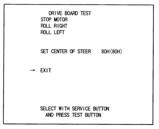 7 - 9 DRIVE BD TEST
Select DRIVE BOARD TEST to have the following screen displayed. This test allows the movement of motor, etc., to be checked and the Steering Wheel Volume setting to be performed.
Press the Service Button to select each item and press the Test Button to cause the selected item's movements to be performed.
STOP MOTOR: Stops the load subjected to the Steering wheel and the movements of the Motor for reaction. As such, intially selecting this item and pressing the Test Button make no difference superficially. Select ROLL RIGHT or ROLL LEFT below this item, and in the status that the motor is functioning ina certain direction, select the item and press the Test Button to stop movements in that particular direction.
ROLL RIGHT: The motor moves so as to turn the Steering Wheel clockwise.
ROLL LEFT: The motor moves so as to turn the Steering Wheel counterclockwise.
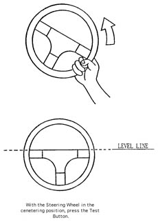
SETTING THE VOLUME
Performs the setting of VOLUME which detects the movements of Steering Wheel as per the figure shown below. When the Steering Wheel Volume is adjusted or replaced, perforom Volume Setting in the following procedure.
SETTING THE STEERING WHEEL VOLUME
1.) Press the Service button to bring the arrow to SET CENTER OF STEER.
2.) Secure the Steering Wheel to the Centering position.
3.) Press the Test Button. Store the Volume Value obtained at this time as Steering Wheel's centering value.