WARNING: Perform the assembly work by following
the procedure herein stated. Failing to comply with the instructions,
for example, inserting the plug into an outlet at the stage not
mentioned in this manual might cause an electric shock.
Assembling should be performed as per this manual. Since this
is a complex machine, erroneous assembling may cause damage to
the machine, or malfunctioning to occur.
When carrying out the assembly work, follow the procedure
in the following sequence:
1. Assembling the cockpits.
2. Securing in place. (Leg leveler adjustment)
3. Wiring connection.
4. Turning the power on.
5. Assembly check.
Note that the master key, cashbox door key, screwdriver, tamperproof
wrench, wrench for M16 hexagon bolt and socket wrench are required
for the assembly work.
1. Place the two cockpits side by side. Position the 1P cabinet,
which has the coin tower and blue decals, on the left-hand side
as you face the monitor. Join the wire connectors together between
the two cabinets. The connectors are located down near the rear
casters. Connect the red end of the fiber cable from the first
cabinet to the black end of the fiber cable from the other cabinet.
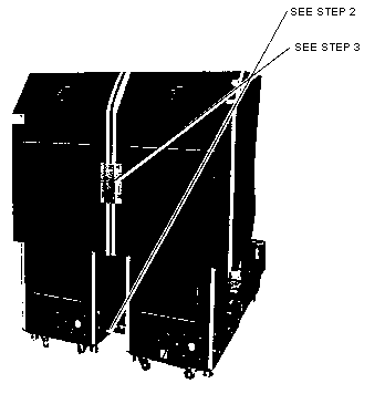
2. Install a bolt on the bottom front and back of the cabinet
on the right side (see picture).
3. Install the bracket on to the back of both cabinets by securing
with four hexagon bolts (see picture).
4. Open the top coin door. Install a bolt through the upper mounting
hole on the right cabinet.
5. After adjusting the leg levelers, join the canopies together
with two nuts and bolts.

For diagram, see next page.
For leg adjustments, see page 8.