7. ACCELERATOR & BRAKE
Be careful so as not to damage wirings. Damaged wiring cancause an electric shock or short circuit accident.
Do not touch places other than those specified. Touching placesnot specified can cause an electric shock or short circuit accident.
If Accel. and Brake operation is not satisfactory, adjustmentof Volume installation position or Volume replacement is needed.Also, be sure to apply greasing to the gear mesh ponion once every3 months.
7 - 1 ADJUSTING AND REPLACING THE V.R.
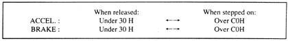
The appropriate value of each V.R. is as follows:
Check Volume values in the Test Mode. (Refer to Service Manual.)Since work is perfonned inside the energized cabinet, be verycareful so as not to touch undesignated portions. Touching placesnot specified can cause electric shock or short circuit.
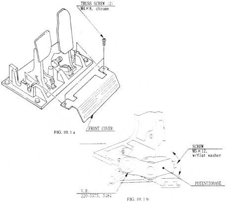
1. Take out the 2 truss screws and remove the Front Cover fromthe Accel. & Brake Unit (FIG. lO. l a).
2. Loosen the screw which secure the Potentiobase, and adjustthe Volume value by moving the Base. (FIG. lO. l b)
3. Secure the Potentiobase.
4. Perform Volume setting in the Volume setting mode.
REPLACING THE VOLUME
1. Turn the power off.
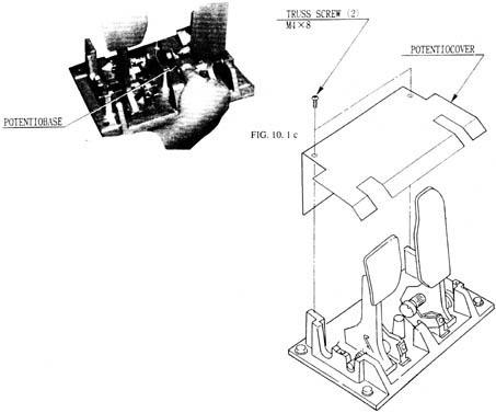
2. Take out the 2 screws and remove the Potentiocover (FIG.10. 1 c).
3. Disconnect the connector of the Volume to be replaced.
4. Remove the screw which secures the Potentiocover (FIG. 10.l b).
5. Remove the Potentiobase together with the Volume as is attached.(FIG. 10. 1. c)
6. Remove the Base and Gear to replace the Volume.
7. In the Test Mode, ensure that the Volume value is appropriate.